|
The engines for the Tiger I were developed specifically for them by the Maybach company of Berlin (Maybach-Motorenbau GmbH). The Maybach company, under the technical leadership of Karl Maybach, produced the engines for all the medium and heavy German tanks of WWII. The first Tiger engine was a V-12 water-cooled gasoline engine with a capacity of 21.33 liters (1302 cubic inches) and a power output of 650bhp at 3000rpm. This engine was the Maybach HL 210 TRM P45. |
|
|
HL = Hochleistungsmotor (high performance motor) TRM = Trockensumpfschmierung mit Schnappermagne (dry sump lubricant with impulse magneto) P = Panzermotor (tank engine) |
|
|
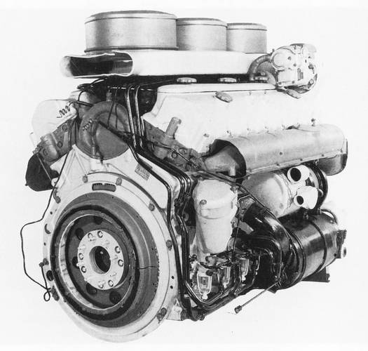
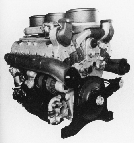
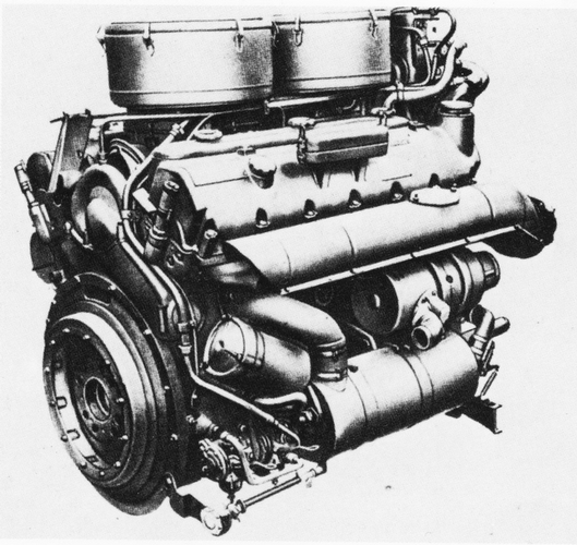
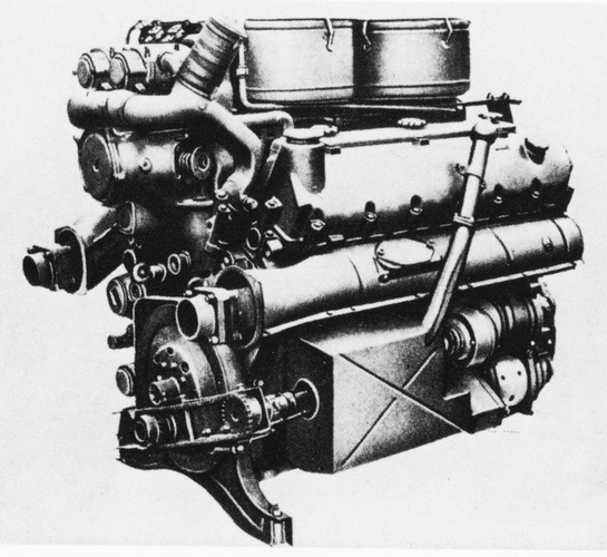
| Front view of HL 210 P45. | Rear view of HL 210 P45. |
|
|
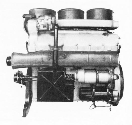
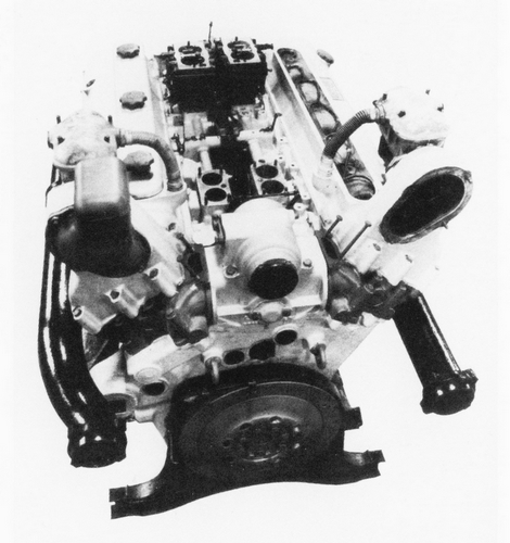
| Side view of HL 210 P45. | Overhead view of HL 210 P45. |
The compact engine put out tremendous power for its size. It was 4 feet long, 3 feet 2 inches wide and 3 feet 1 inch tall without the air cleaners. It was mounted in a sealed compartment at the rear of the Tiger.
The engine was rushed into production without all the bugs being worked out. The engine could not be reliably operated at its maximum power output of 3000 rpms and indeed the operating manual given to the Tiger crews, the Tigerfibel, recommended no more than 2600 rpms. It soon became obvious that the Tiger I was seriously underpowered. Because of the tight engine compartment and other technical limitations it was impossible to install a physically larger, more powerful motor. As a result the original engines displacement was increased by replacing the aluminum cylinder block with a cast iron block and boring it out to 23.88 liters (1457 cubic inches). This increased the weight of the motor but also increased the rigidity. The result was a gain in power to 700bhp at 3000rpm. The new engine was designated the Maybach HL 230 TRM P45.
|
|
| Front view of HL 230 P45. | Rear view of HL 230 P45. |
Only the first 250 Tigers had the HL 210 engine. But even the power increase from the HL 210 to the HL 230 was not enough. While it was comparable in speed to other German tanks of the time, it was still slower than many of its adversaries, such as the Russian T34. It also had a high fuel consumption rate of approximately 2.75 gallons per mile. Since the total fuel capacity of the four fuel tanks was around 125 gallons (568 liters), the operational range of a Tiger I was limited and refueling stops had to be frequent, especially when traveling off road. German logistic plans expected the Tiger to be able to travel 121.2 miles (195km) on road and 68.4 miles (110km) off road before refueling.
The following technical description is taken from a British Military Intelligence report entitled
“Preliminary Report No 19
PzKw VI (Tiger)
Military College of Science
SCHOOL OF TANK TECHNOLOGY
November 1943”
|
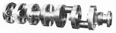
ENGINE The aluminum crank case and cylinder block casting houses a circular web crank shaft in seven roller bearings. The cylinder liners are of the wet type having two rubber sealing rings, with the usual drain hole between them. At the top, a flange recessed into the cylinder block gives the necessary location and a slight spigot stands up into the combustion chamber. Pistons are of aluminum and are carried on steel connecting rods machined all over and forked to permit left and right banks to share the same journal. An interesting feature of design noted here is that the web of the “H” section of the forked connecting rod is in line with the crankshaft. The forked rod carries a bearing shell which bears on the full length of the crank pin and receives on its outside diameter the unforked rod from the opposite bank. The big-end nuts are serrated on their circumference instead of being hexagonal.
The camshaft and all auxiliaries are driven by straight spur timing wheels from the opposite end of the crank shaft to the flywheel, which is of steel, machined all over and with starter ring teeth machined on it. A normal torsional oscillation damper is fitted at the timing end of the crank shaft outside the crank case. The cylinder heads, which are of cast iron, and one to each bank have hemispherical combustion chambers.
VALVES
CARBURETTORS
GOVERNOR
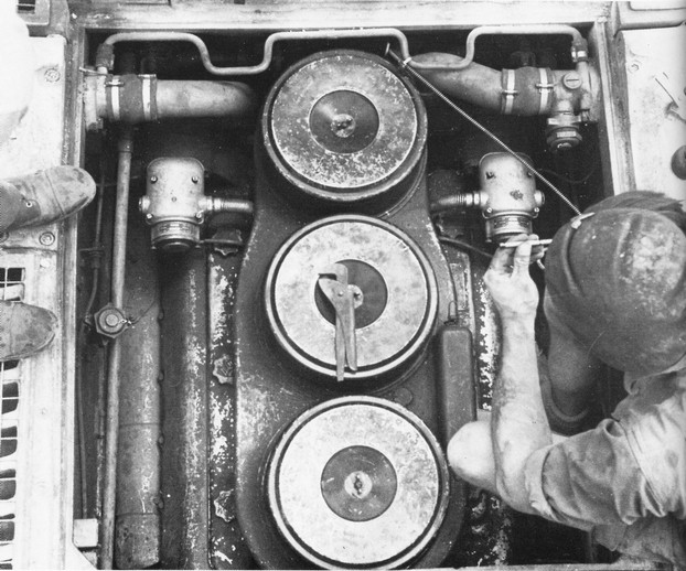
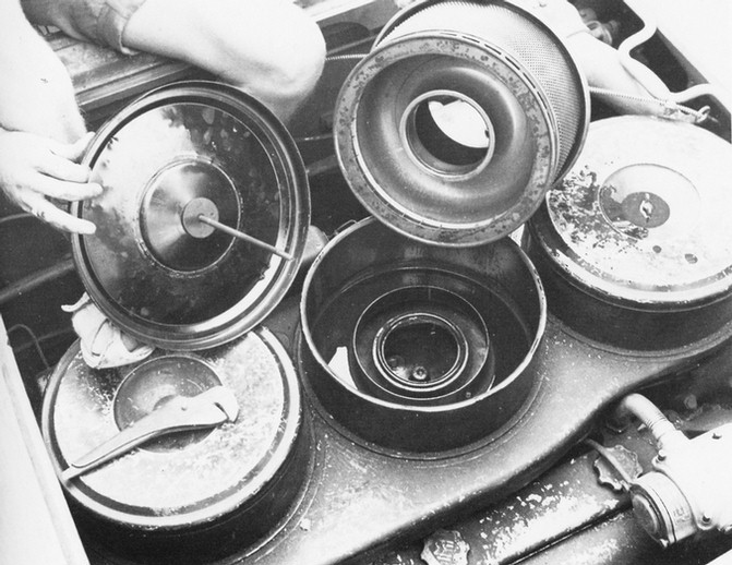
AIR CLEANERS The pre-cleaners are of the vertical tube type with tangential intakes at the sides and the outlet at the top. The oil bath cleaners are of the orthodox pattern with annular gauze elements.
PETROL PUMPS
EXHAUST
FUEL TANKS The tanks on each side are coupled, the upper wedge shaped tanks feeding the lower by gravity. The filler caps are accessible on each side by the removal of a circular B.P. screwed cover. An asbestos screen is fitted to the engine side of each rectangular tank.
COOLING
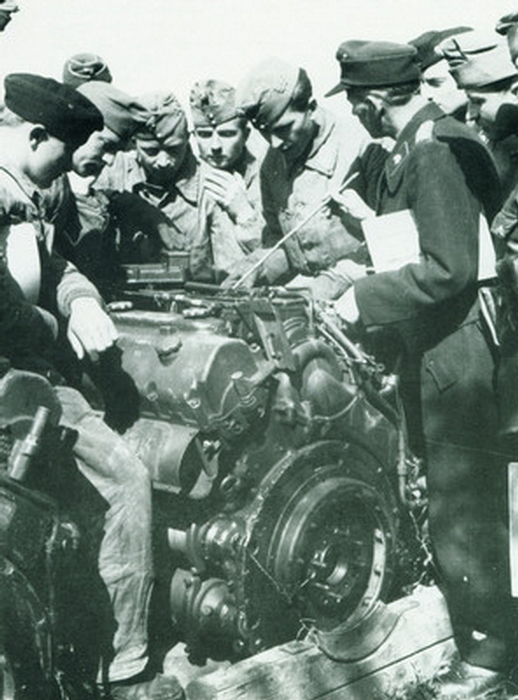
Trainees receiving instruction on the Tigers motor.
IGNITION
STARTERS
ACCUMULATORS They are normally connected in parallel but a series/parallel switch permits a change over to 24V for starting.
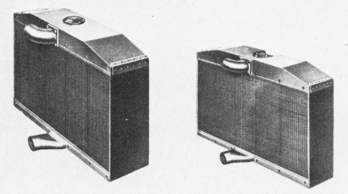
RADIATORS The radiators are coupled and a common filler cap is provided in the near-side unit. A pressure relief valve is mounted on the offside radiator and a balance pipe maintains equal pressure in the two radiators. Relief valves are fitted in the water inlet and outlets to the engine to avoid air locks when external hot water circuit is in use. The capacity of the water system is approximately 16 gallons.
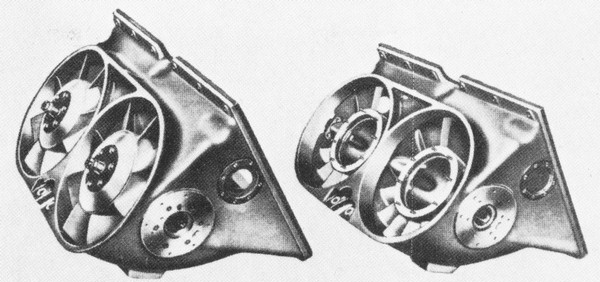
FANS
LUBRICATION
WATER PUMP |
|
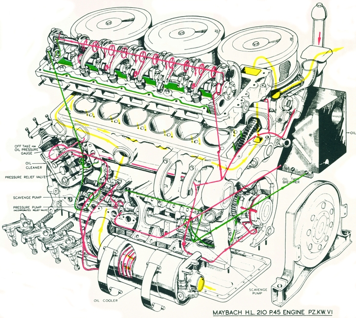
| HL 210 fluid flow. RED = oil feed. GREEN = oil return. YELLOW = water. |
Even though the report is on the HL 210, most of it also applies to the HL 230, the main difference being the cast iron block, the location of the ignition magnetos, and the number of air filters. The HL 210 had three air filter housings. The HL 230 only had two.
So while it could have been more reliable, the Tigers Maybach engine was still a remarkable feat of engineering. Rushed into production and forced into the tight confines of the Tigers engine compartment, the motor performed as well as could be expected under the conditions in which it had to operate.
|
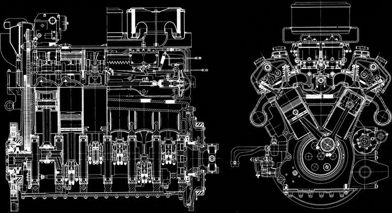
| HL 210 cutaway schematics. |