|
|
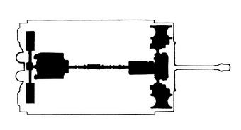
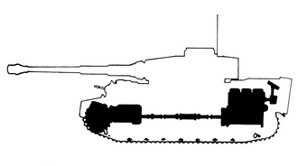
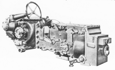
| Drivetrain seen from the top. | Drivetrain from the side. |
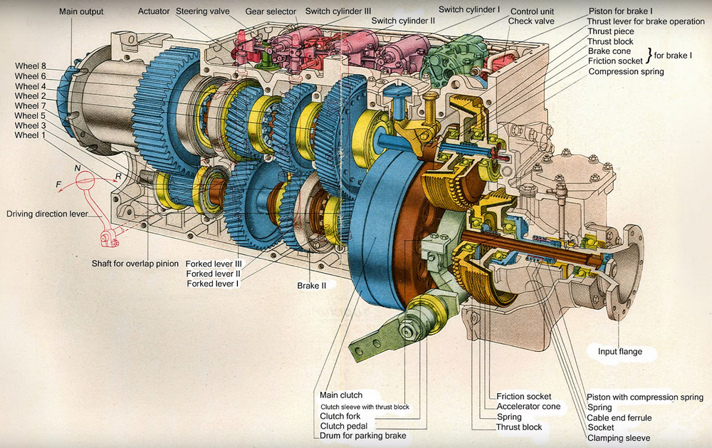
The Tiger I incorporated two new systems for German tanks. The first was the hydraulically-controlled pre-selector gearbox and semi-automatic transmission. The second was the steering unit.
Power was transmitted from the rear-mounted engine via a driveshaft under the main compartment floor which was connected to a gearbox located to the right of the driver. The gearbox was a Maybach type 40 12 16 Olvar pre-selector manufactured by either Maybach, Zahnradfabrik or Adterwerke under license from Olvar-Getriebe. It had eight forward and four reverse gears. The gearbox also had power takeoffs for the turret hydraulic drive and the bilge pump. With light controls, the gearbox was easy to operate. Drive was transmitted to each of the front drive sprockets by spur reducing and epicyclic gears inside the sprockets. The final drive was manufactured by Henschel und Sons.
|
|
|
| Drivetrain seen from the top. | Drivetrain from the side. |
The Argus Lenkapparat L, ST, 0, 2 steering unit was designed by Henschel based on the British Merritt-Brown type. Mounted transversely in the bow of the tank, it was fully regenerative and continuous, with the steering drive connected to a final reduction gear in each drive sprocket. The Tiger was the first German tank to have an actual steering wheel, which was easy to use thanks to hydraulic assistance. There were, however, levers on each side of the driver that actuated 55cm Argus-Werke disc brakes on each drive shaft. This served as an emergency steering system. These same brakes also served as the main braking system when operated by foot pedal controls.
|
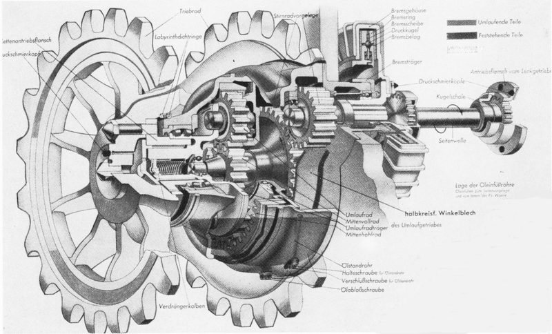
| The complete gearbox and steering unit. |
The following technical description is taken from a British Military Intelligence Summary dated November 1943:
|
“GEARBOX
The same withdrawal fork is operated by the clutch pedal. A small cone clutch on the input side of the main shaft and the rear end of the lay shaft are geared together and operated by hydraulic pressure giving synchronization of the lay shaft with the engine speed. The input shaft also drives, through two gears, a fore and aft shaft on which are mounted two oil pumps, which provide the pressure necessary for hydraulic operation. Another unit driven from this shaft is the engine rev counter. Hydraulically operated brake shoes are provided for the slowing of the main clutch and the second gear from the input end on the main shaft, and a hydraulic device adjusts the throttle opening as required. An easily accessible oil filter is provided which serves both gearbox and steering unit which have a common oil level; the level is checked by a dip-stick on the gearbox and replenished through a filler cap. The oil capacity is 32 litres (7 gallons). A metal strip on the gearbox cover bears the following figures:
which can be explained as follows: The figures within the diamonds correspond to the hydraulic cylinder of each selector. The figures before the diamonds in each case represent the number of the gear engaged with the selectors in question in the forward position. The figures after the diamonds represent the gear engaged with the selectors in the rear position. The table thus gives the position of each set of selectors for each gear. The overall ratios from gearbox input flange to steering unit output flanges, including therefore spiral bevel reduction on the gearbox output shaft, are:
The four ratios of reverse correspond to, but are lower than, the four lowest forward gears.
STEERING UNIT The direction and speed rotation of the sun wheel and the choice of left or right hand sides are governed by the engagement of two or four hydraulically operated multi-disc clutches. These clutches connect the sun wheels through a lay shaft meshing with the small bevel on the extension of the gearbox input shaft. In this way a choice of two speeds both proportional to engine speed, is imposed at will upon the sun wheel of the epicyclic whose annulus is already rotating at a multiple of engine speed according to the gear engaged. In addition, in neutral with no output from the main gearbox bevel, a drive is still obtained from the bevel on the extension of the gearbox input shaft, and this produces with the engagement of the appropriate steering clutch opposing rotations of left and right sun wheels. As the annuli are unable to rotate in opposite directions owing to their being secured to the same shaft this opposite rotation of the sun wheel, of necessity, produces opposite rotation of the output flanges, resulting in a neutral turn. For one full revolution of both output flanges the gearbox input flange performs 117 revs. Oil pressure from a pump driven by an extension of the fore and aft gearbox shaft is admitted to the required steering clutches through ports in the steering assembly casing, the opening of which is controlled by a piston valve. Movement of piston valve is governed by the driver's steering wheel. In this way two distinct radii of turn are available for each gear engaged, and identical for left and right turns. A mushroom shaped knob on the gearbox casing operates hydraulically a brake on one section of the main shaft, thereby eliminating clutch drag and making the neutral turn more positive. The tank can also be steered when required by steering levers on each side of the driver which operate the right and left brake assemblies.
FINAL DRIVE |
Even though its powertrain systems might not have been the most reliable, when they worked the Tiger was quite mobile for its size and weight. It could pivot in place, completely turning around in a distance of 3.44 meters (11.28ft). As the table below shows, the Tigers speed was comparable to other, smaller German tanks except for the Panther:
| Model | On-road Speed | Off-road Speed |
| Panzer III | 40 km/h | 18 km/h |
| Panzer IV | 40 km/h | 20 km/h |
| Tiger I | 38 km/h | 20 km/h |
| Panther | 46 km/h | 24 km/h |
Thus with the new transmission and steering systems, the extremely large and heavy Tiger I could be easily driven. The belief that the Tiger was a slow, lumbering giant is a myth.
|
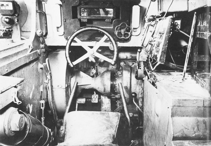
| The drivers position. From the left is the handbrake lever, left steering stick, steering wheel, right steering stick and the gear preselector lever. The small wheel to the right of the steering wheel is for raising and lowering the visor armor outside the drivers viewport. |